Choosing the right Vacuum Furnace Heat Treatment system in 2026 requires more than comparing chamber size or purchase price. Materials, part geometry, production volume, surface requirements, energy use, and maintenance access all matter. A titanium component with thin walls needs different control from a heavy tool-steel die. Small temperature errors can change hardness, distortion, or fatigue performance.
George E. Totten, a recognized heat-treatment authority, describes heat treatment as “the controlled heating and cooling of a material to obtain desired properties.” That principle remains practical today. A reliable furnace should provide stable temperature uniformity, accurate vacuum measurement, controlled gas quenching, and documented process records. Ask for temperature-uniformity surveys, calibration evidence, and references from comparable applications. Do not rely on impressive specifications alone.
The details matter.
Experienced engineers also inspect loading patterns, fixture design, pump performance, and cooling time. These factors can decide whether results are repeatable on Monday morning, not merely impressive during a demonstration. Energy efficiency deserves attention, but lower consumption should never excuse weak process control. A cheaper furnace may create higher costs through rework, distortion, or inconsistent hardness.
No single furnace fits every factory. That is the uncomfortable part. The best selection may require pilot trials, supplier audits, and a revised production plan. Buyers should compare measurable results, not confident promises. This guide examines the technical, financial, and operational questions that can make Vacuum Furnace Heat Treatment a dependable investment in 2026.
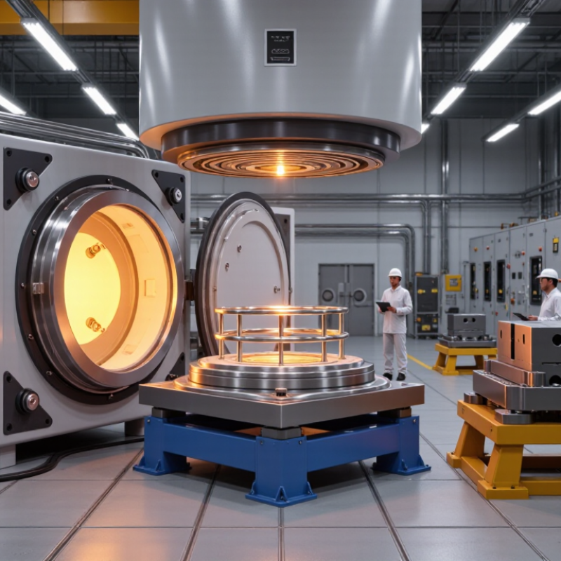
How to Choose Vacuum Furnace Heat Treatment in 2026?
Start with the workpiece, not the furnace catalogue. Steel parts often need 300–900°C for stress relief, hardening, tempering, or annealing. Tool steels may require 1,000–1,200°C, with careful control of soaking time. Titanium demands a cleaner atmosphere because oxygen and nitrogen can embrittle its surface. Many titanium cycles operate between 600 and 950°C. Nickel-based and other high-temperature alloys may require temperatures approaching 1,300°C.
Temperature is only one decision. A large steel gear needs uniform heating, stable support, and controlled gas quenching to limit distortion. Thin titanium brackets need gentle loading and accurate thermocouples near critical sections. For reactive alloys, low leakage rates and reliable vacuum measurement are essential. Partial-pressure argon can improve heat transfer, but excessive gas flow may disturb lightweight components.
In practice, load size changes the cycle. A furnace reaching 1,300°C may perform poorly with unevenly packed parts. Review the alloy specification, permitted hardness range, surface condition, and cooling rate before selecting equipment. Record actual part temperatures, not only chamber readings. That detail is often missed. A perfect recipe on paper can still produce soft corners, discoloration, or cracking. The correction may involve fixturing rather than a higher temperature. Mistakes happen, especially when mixed alloys share one load.
| Workpiece / Material Family | Typical Examples | Primary Vacuum-Furnace Process | Typical Temperature | Recommended Atmosphere and Pressure | Cooling Method | Main Objective | Key Selection Considerations |
|---|---|---|---|---|---|---|---|
| Low-Carbon and Low-Alloy Steel | Construction steel, carburizing steel, machine components | Vacuum carburizing Quench and temper | 880–980°C | High vacuum for heating; hydrocarbon pulses for carburizing; high-purity nitrogen or helium for quenching | Gas quench followed by tempering at approximately 150–220°C | High surface hardness with a tough, low-carbon core | Useful for gears and shafts. Case depth depends on carburizing time, temperature, and carbon potential. Avoid excessive surface carbon, which can increase retained austenite and cracking risk. |
| Medium-Carbon and Alloy Steel | Quenched-and-tempered shafts, pins, dies, structural machine parts | Austenitizing Oil-free gas quench and temper | 800–900°C | Vacuum heating followed by nitrogen, helium, or argon backfill for inert cooling | Pressurized gas quench; temper commonly at 450–650°C | Balanced strength, hardness, and toughness with reduced oxidation | Section thickness and alloy hardenability determine the required gas-quench pressure. Large cross-sections may require slower cooling or a separate quench strategy. |
| Cold-Work Tool Steel | High-chromium tool steel, punch and die steel, wear-resistant tooling | Hardening Double or triple tempering | 1,000–1,080°C | High vacuum or partial-pressure inert gas; avoid decarburization and uncontrolled oxidation | High-pressure gas quench, followed by tempering at approximately 150–550°C | High wear resistance, dimensional stability, and compressive strength | Preheating steps reduce thermal shock. Multiple tempers are often used to transform fresh martensite and stabilize dimensions. |
| High-Speed Steel | Molybdenum or tungsten high-speed cutting-tool steel | High-temperature hardening Multiple tempering | 1,180–1,260°C | High vacuum with controlled partial pressure; protective gas during high-temperature holding and cooling | Rapid gas quench, commonly followed by two or three tempers around 540–570°C | Secondary hardness and hot-wear resistance | Temperature uniformity is critical because the austenitizing range is narrow. Excessive soaking can cause grain growth or distortion. |
| Hot-Work Tool Steel | Hot-work die steel, extrusion tooling, forging dies | Vacuum hardening Tempering and optional stress relief | 980–1,050°C | Vacuum or inert partial pressure with high-purity quench gas | High-pressure gas quench; temper commonly at 550–650°C | Hot strength, thermal-fatigue resistance, and toughness | Use controlled heating and staged preheating for complex dies. Uniform gas flow is important for minimizing distortion in large tooling. |
| Martensitic Stainless Steel | Hardenable stainless cutlery, valves, shafts, surgical instruments | Vacuum hardening Tempering | 980–1,070°C | High vacuum or inert partial pressure; prevent chromium-oxide scale and surface contamination | Gas quench followed by tempering, typically 150–650°C depending on grade and target properties | Corrosion resistance combined with high hardness and strength | Carbon and alloy content strongly affect the hardening temperature. Overheating may promote grain growth, retained austenite, or reduced corrosion performance. |
| Austenitic Stainless Steel | Corrosion-resistant process parts, medical and food-contact components | Solution annealing Stress relief when specified | 1,040–1,150°C | Vacuum or high-purity inert atmosphere; use clean, low-contamination fixtures | Rapid gas cooling to suppress carbide precipitation; water cooling may be required for some large sections | Restore corrosion resistance and dissolve unwanted precipitates | Cooling must be sufficiently rapid through the sensitization range. Vacuum processing does not replace the need for correct alloy-specific cooling rates. |
| Precipitation-Hardening Stainless Steel | High-strength corrosion-resistant components and aerospace hardware | Solution treatment Age hardening | 1,020–1,050°C solution treatment; 480–620°C aging | Vacuum or inert atmosphere with controlled cooling | Gas cooling, air cooling, or sub-zero treatment depending on grade; aging follows solution treatment | High strength with controlled corrosion resistance | Strength is highly dependent on aging temperature and time. Follow the material specification because different conditions can produce substantially different hardness and toughness. |
| Alpha Titanium Alloys | Commercially pure titanium and alpha titanium components | Stress relief Annealing | 540–760°C | High vacuum or ultra-high-purity argon; minimize oxygen, nitrogen, and hydrogen pickup | Furnace cooling or controlled inert-gas cooling | Reduce residual stress and improve dimensional stability | Titanium reacts readily with oxygen and nitrogen at elevated temperature. Clean surfaces, compatible fixtures, and tight atmosphere control are essential. |
| Alpha-Beta Titanium Alloys | Common aerospace-grade titanium components and high-strength fasteners | Stress relief Annealing or sub-transus treatment | 650–900°C | High vacuum or high-purity argon; avoid long exposure at temperatures that promote excessive alpha-case formation | Air, inert-gas, or furnace cooling according to the required microstructure | Control residual stress, strength, ductility, and fatigue performance | Processing below or above the beta transus produces different microstructures. Temperature uniformity and cooling rate should be validated for each section size. |
| Beta Titanium Alloys | Metastable beta titanium used for high-strength lightweight parts | Solution treatment Age hardening | 760–900°C solution treatment; 480–650°C aging | High vacuum or high-purity argon with very low residual oxygen and moisture | Rapid cooling after solution treatment, followed by controlled aging | High specific strength and adjustable mechanical properties | Small changes in solution and aging conditions can change the balance of beta, alpha, and metastable phases. Atmosphere contamination can reduce ductility and fatigue performance. |
| Nickel-Based Superalloys | Hot-section components, high-temperature fasteners, turbine and furnace parts | Solution treatment Age hardening | 1,050–1,300°C | High vacuum or high-purity inert gas; partial-pressure operation may limit evaporation of volatile elements | Controlled gas cooling, air cooling, or staged cooling depending on alloy and desired precipitate structure | High-temperature strength, creep resistance, and oxidation resistance | Temperature uniformity is especially important near the solidus temperature. Excessive heat can cause incipient melting, while insufficient cooling can alter precipitation behavior. |
| Cobalt-Based Heat-Resistant Alloys | Wear-resistant and high-temperature components | Solution annealing Stabilizing or aging treatment | 1,050–1,250°C | Vacuum or high-purity inert atmosphere; use clean, non-reactive fixtures | Gas cooling or controlled furnace cooling based on the specification | Improve high-temperature stability, wear resistance, and service life | Control of carbon, carbide distribution, and grain size is important. The furnace should provide stable temperature control across the full load. |
| Aluminum Alloys | Heat-treatable structural aluminum components | Solution heat treatment Quenching and artificial aging | 450–550°C solution treatment; 120–200°C aging | Air or inert atmosphere is commonly preferred; vacuum is mainly selected for special contamination-sensitive applications | Rapid gas or liquid quench according to the alloy and section thickness | Increase strength through precipitation hardening | Aluminum has a narrow solution-treatment window. Excessive temperature can cause incipient melting, while slow quenching can reduce achievable strength. |
| Copper and Copper Alloys | Electrical contacts, tooling, heat exchangers, and conductive components | Annealing Stress relief or solution treatment | 300–900°C | Vacuum or inert gas where oxidation and surface discoloration must be minimized | Furnace cooling, air cooling, or controlled inert-gas cooling | Restore ductility, reduce residual stress, and maintain surface cleanliness | Some copper alloys contain volatile or oxidation-sensitive elements. Select the atmosphere and cooling rate based on alloy composition and electrical requirements. |
| Cemented Carbide and Hardmetal Assemblies | Cutting inserts, wear components, and composite tooling | Vacuum brazing Stress-relief heating | 600–1,100°C, depending on filler metal | High vacuum or inert atmosphere suitable for the selected brazing filler | Controlled furnace cooling to limit thermal shock and residual stress | Join carbide to steel or other substrates without oxidation or flux residue | Match thermal expansion between joined materials. Joint clearance, filler-metal melting range, and heating rate strongly affect joint quality. |
| Powder-Metal and Additively Manufactured Steels | Tooling inserts, lattice structures, and near-net-shape steel parts | Vacuum stress relief Hardening and tempering | 300–1,100°C, depending on alloy and process route | Vacuum or inert atmosphere; low residual oxygen and moisture are important for porous or finely featured parts | Controlled gas cooling, furnace cooling, or staged cooling | Reduce residual stress, control porosity-related distortion, and achieve target hardness | Part geometry, density gradients, and build orientation can affect distortion. Use representative test coupons to validate the complete thermal cycle. |
